X1206-v1.1 Hardware & Installation
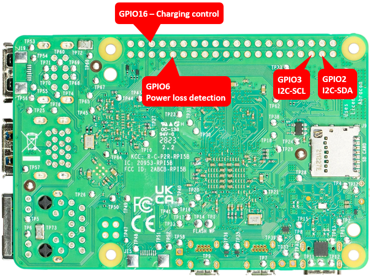
1. Raspberry Pi GPIO Used
PIN# | GPIO | Functions
3 | GPIO2 | I2C-SDA, battery fuel-gauge systems - reading battery voltage and percentage
5 | GPIO3 | I2C-SCL, battery fuel-gauge systems - reading battery voltage and percentage
31 | GPIO6 | AC power loss & power adapter failure detection, Low-power supply failed, High-power supply OK
36 | GPIO16 | Control battery charging, High-charging disabled, Low-charging enabled
*The UPS connects to the Pi GPIO via pogo pins. If the I2C address (0x36) is not detected or fails to read AC power state or control charging, please ensure to clear the leads of the pins used on the GPIO header from the bottom of the Raspberry Pi PCB and then reinstall it.
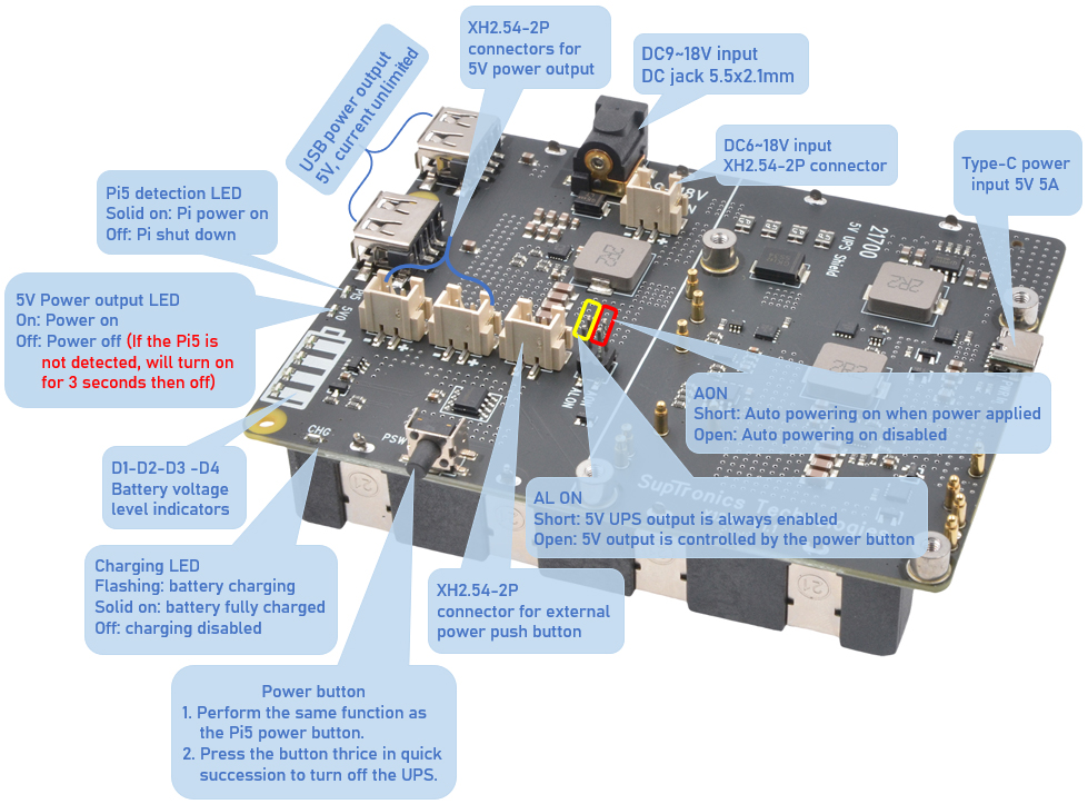
2. Battery Voltage Level Indicators
Battery Voltage Range (V) | D1 | D2 | D3 | D4 | Remark
3.87-4.2 | ON | ON | ON | ON | Discharging levels of 100%
3.7-3.87 | ON | ON | ON | OFF | Discharging levels of 75%
3.55-3.7 | ON | ON | OFF | OFF | Discharging levels of 50%
3.4-3.55 | ON | OFF | OFF | OFF | Discharging levels of 25%
Below 3.4 | OFF | OFF | OFF | OFF | Low battery
Required Hardware
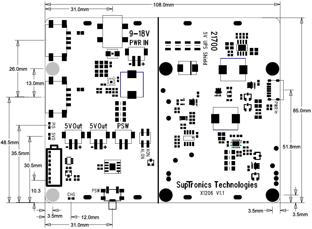
- X1206 UPS Shield
- Raspberry Pi 5 Model B
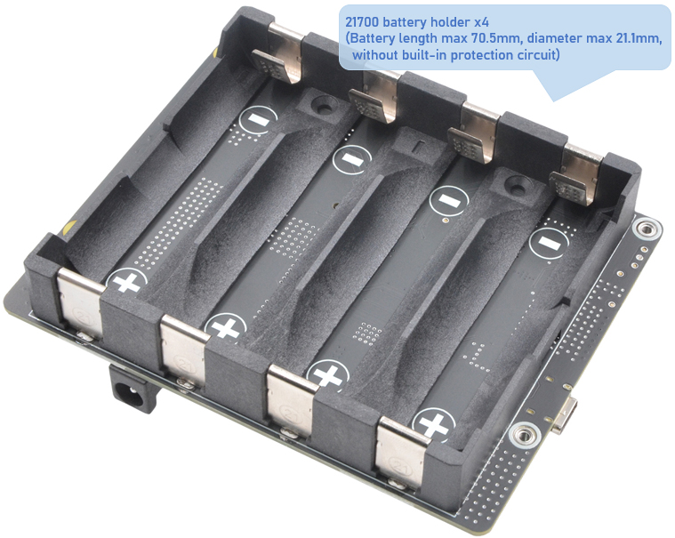
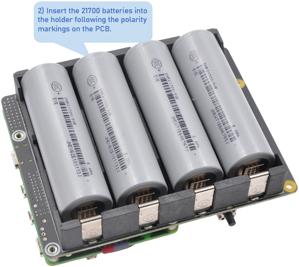
- 21700 battery without built-in protection circuit (2~4 pcs)
- Power Supply (27W USB-C or 6~18Vdc DC plug 5.5x2.1)
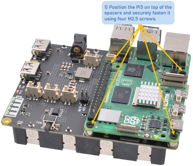
Hardware Installation
Return to Product Page:
X1206 Quad 21700 UPS Power Management Board for Raspberry Pi 5
Other Documentation Pages:
X1206 Quad 21700 UPS Power Management Board for Raspberry Pi 5
Other Documentation Pages:
- + Overview
For further assistance or inquiries, please reach out to our support team at info@edgecase.shop or sales@edgecase.shop. We are here to help you with any questions you might have.